IV.

Constructing Hangars 2 and 3

A huge blimp hangar, consisting of a parabolic arch roof flanked by wide concrete towers, which is under construction and covered in scaffolding.
Full view of the north end of Hangar 2 showing the box girder construction, Earl W. Heple & J.H. Pomeroy Inc., Contractors, U.S. Navy, 1943. Courtesy Moffett Field Historical Society Museum, photo no. 357 July 14, 1943

In June 1940, the U.S. Congress passed Public Law 635, known as the “10,000 Plane Program,” in response to the escalating war in Europe. One of the goals of that initiative was to expand the nation’s lighter-than-air (LTA) program by constructing new coastal facilities and 48 non-rigid airships, or blimps, that would be used for submarine surveillance operations. The attack on Pearl Harbor on December 7, 1941, redefined and accelerated those initial plans.

New LTA hangars were originally going to be made with steel. The Second Deficiency Appropriation Bill for 1941 regulated the use of strategic materials, and the Navy determined that most metal would be utilized for its ambitious wartime shipbuilding and weapons production efforts. As a result, the Department of the Navy Bureau of Yards and Docks designed and engineered a standardized set of ingenious plans for the world’s largest freestanding wood-frame structures. Between 1942 and 1943, 17 nearly identical timber and concrete hangars were built at ten different U.S. Naval bases. Each enormous building was large enough to house a squadron of six to ten blimps, depending on their type.

Lighter-Than-Air Hangar Roof Truss Details, Naval Air Station Santa Ana, California, Department of the Navy Bureau of Yards & Docks, 1942
Typical Cross Section and Details, L.T.A.A. Timber Hangar, Department of the Navy Bureau of Yards & Docks, 1942, drawing no. B4275
Standard Lighter-Than-Air Hangar Stairs, Catwalk and Details, Department of the Navy Bureau of Yards & Docks, 1942, drawing no. AM4-0047-S164
Standard Lighter-Than-Air Hangar Details at Door Girder & Towers, Department of the Navy Bureau of Yards & Docks, 1942, drawing no. AM4-047-S149
Standard Lighter-Than-Air Hangar Wood Construction 3’-6” Steel Rolling Door 220FT. × 120FT. Opening, Department of the Navy Bureau of Yards & Docks, 1942
Lighter-Than-Air-Hangar Towers for Steel Doors 220FT. × 120FT. Opening, Naval Air Station Santa Ana, California, Department of the Navy Bureau of Yards & Docks, 1942, drawing no. 236,681
Standard Lighter-Than-Air Hangar Sections and Details, Portal Bracing & Truss Anchorage, Department of the Navy Bureau of Yards & Docks, 1942, drawing no. AM04-0047-S157
Standard Lighter-Than-Air-Hangar Wood Construction Details of Office Lean-to, Department of the Navy Bureau of Yards & Docks, 1942, drawing no. AM4-0047-S155
Hangar 3. Plan of Offices and Shops (Architectural) for Operations Dept., Department of the Navy Bureau of Yards & Docks, 1943, drawing no. AM4-0047-A45
Standard Lighter-Than-Air Hangar Framing Plans, Department of the Navy Bureau of Yards & Docks, 1942, drawing no. AM4-0047-S156
Isometric L.T.A. Hangar No. 2, Replace Roofing Hangars 2 and 3, Department of the Navy Bureau of Yards & Docks, 1956
Isometric L.T.A. Hangar No. 3, Replace Roofing Hangars 2 and 3, Department of the Navy Bureau of Yards & Docks, 1956 

Control of Moffett Field was transferred from the U.S. Army back to the Navy in 1941, and the site became dedicated to training the LTA pilots and crews that patrolled the coastlines of California, Oregon, Washington, Hawaii, and Alaska. Two wood hangars were rapidly constructed so that they could be used by the Navy Station Assembly and Repair Department to assemble, store, and maintain the blimps and untethered “free balloons” that were a critical part of the LTA pilots’ aviation exercises.

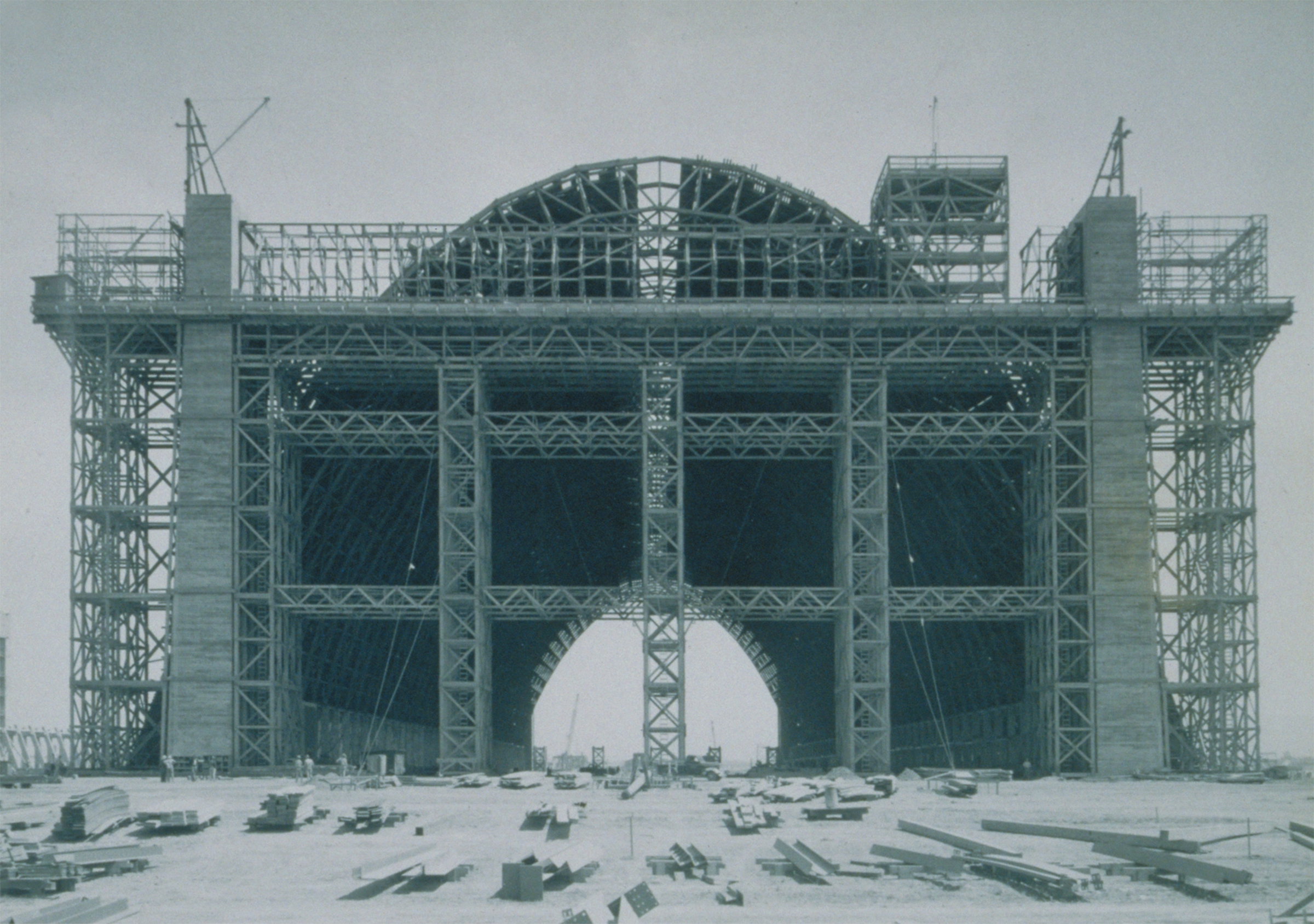
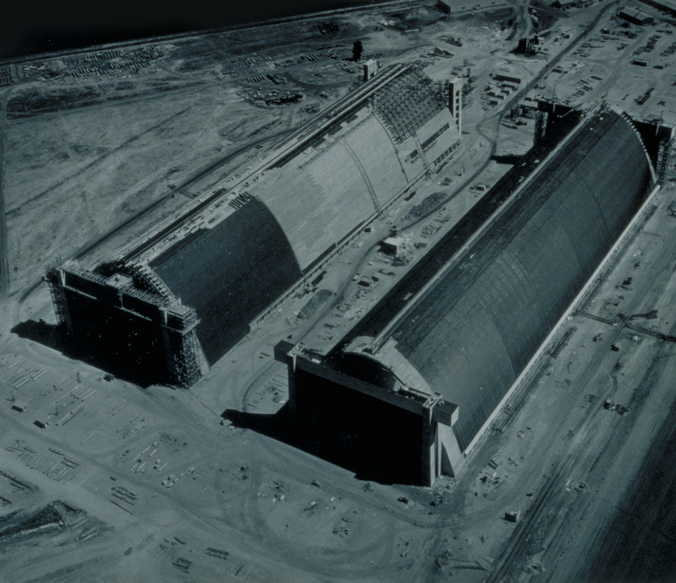
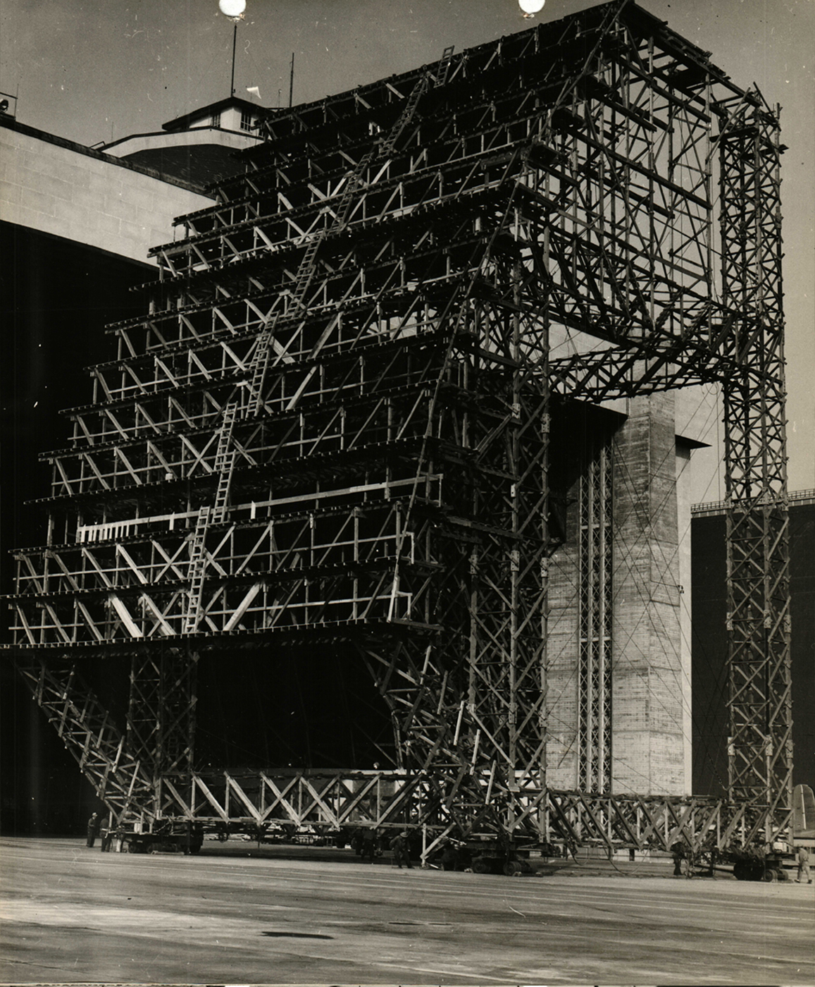
Hangar 2 and Hangar 3 were built on the east side of the airfield in a side-by-side configuration that was on axis with and parallel to Hangar 1, located on the opposite side of the runways. The construction of Hangar 2 began on August 22, 1942. It was completed in 372 days and cost approximately $2.5 million. The Hangar 3 project started on November 3, 1942. It was built in 208 days at an expense of about $1.8 million. Both structures were finished in 1943, thanks to an efficient production process that included the onsite assembly of prefabricated trusses.

A birds-eye view of the early phase of construction for 2 blimp hangars located side-by-side. 4 concrete door towers rise from the Hangar 2 site.
Aerial shot of Hangars 2 and 3 under construction with an airship in the distance, Earl W. Heple & J.H. Pomeroy Inc., Contractors, U.S. Navy, 1943. Courtesy Moffett Field Historical Society Museum, photo no. SNVL 1617
Sections of large wood trusses being built onsite for the construction of 2 blimp hangars.
Construction of an arch for Hangar 2, Earl W. Heple & J.H. Pomeroy Inc., Contractors, U.S. Navy, 1943. Courtesy Moffett Field Historical Society Museum and Naval History & Heritage Command, photo no. UA 51.01.21 #235
A birds-eye view of rows of dozens of large wood trusses being built onsite for the construction of 2 blimp hangars.
Full view of assembly line for the erection of trusses for Hangar 2, Earl W. Heple & J.H. Pomeroy Inc., Contractors, U.S. Navy, 1943. Courtesy Moffett Field Historical Society Museum, photo no. 337 May 5, 1943
The foundation and concrete towers for Hangar 3 beginning to rise from the construction site.
Three quarter view of the Hangar 3 foundation and door tower construction, Earl W. Heple & J.H. Pomeroy Inc., Contractors, U.S. Navy, 1943. Courtesy Moffett Field Historical Society Museum, photo no. 0322 1943
A concrete tower rising on each corner of the construction site for Hangar 3.
View down the centerline of Hangar 3 showing the foundation on both sides, Earl W. Heple & J.H. Pomeroy Inc., Contractors, U.S. Navy, 1943. Courtesy Moffett Field Historical Society Museum, photo no. 349 June 17, 1943
Two completed door towers and wood parabolic roof trusses being assembled by a large movable scaffolding at the Hangar 3 construction site.
View from the south end of Hangar 3 showing the Traveler being moved into place with some lower arch sections already in place, Earl W. Heple & J.H. Pomeroy Inc., Contractors, U.S. Navy, 1943. Courtesy Moffett Field Historical Society Museum, photo no. 352 July 17, 1943
A view down the length of a construction site revealing the completed roof of Hangar 2 and the in-process assembly of the roof trusses for Hangar 3.
Full view of Hangars 2 and 3 taken from the south end. Earl W. Heple & J.H. Pomeroy Inc., Contractors, U.S. Navy, 1943. Courtesy Moffett Field Historical Society Museum, photo no. 358 July 26, 1943
A group of Hangar 2 construction workers assemble a wide horizontal surface made of timber planks adjacent to the top end of the arched roof truss.
View showing the construction of the south end box girder of Hangar 2, Earl W. Heple & J.H. Pomeroy Inc., Contractors, U.S. Navy, 1943. Courtesy Naval History & Heritage Command and Moffett Field Historical Society Museum, Seabee Archive, photo no. SNVL 1961
A tall and wide movable scaffolding tower with a construction crane on top used to assemble the wood trusses for Hangars 2 and 3.
Full view of the Traveler, Earl W. Heple & J.H. Pomeroy Inc., Contractors, U.S. Navy, 1943. Courtesy Naval History & Heritage Command and Moffett Field Historical Society Museum, Seabee Archive, photo no. SNVL 1960

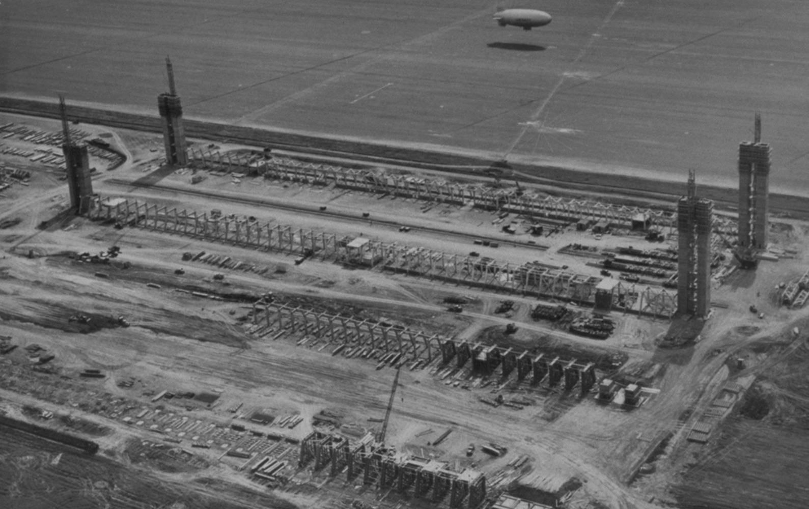
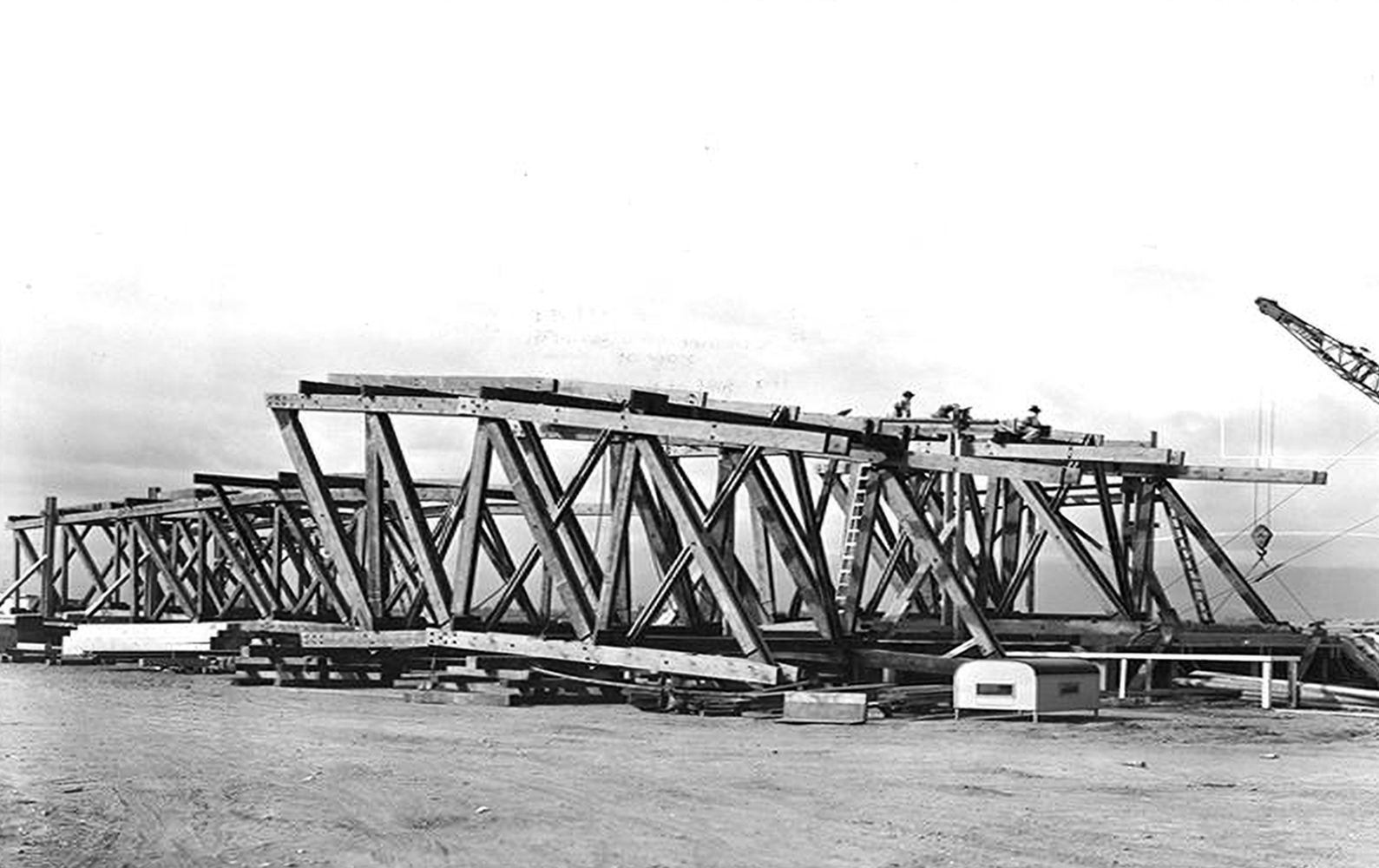
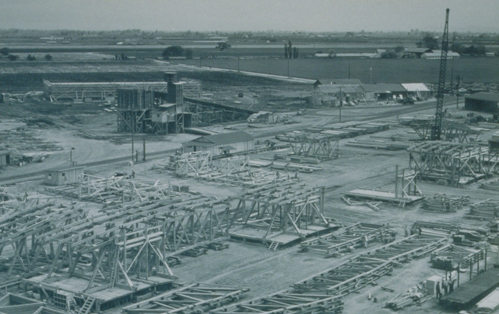
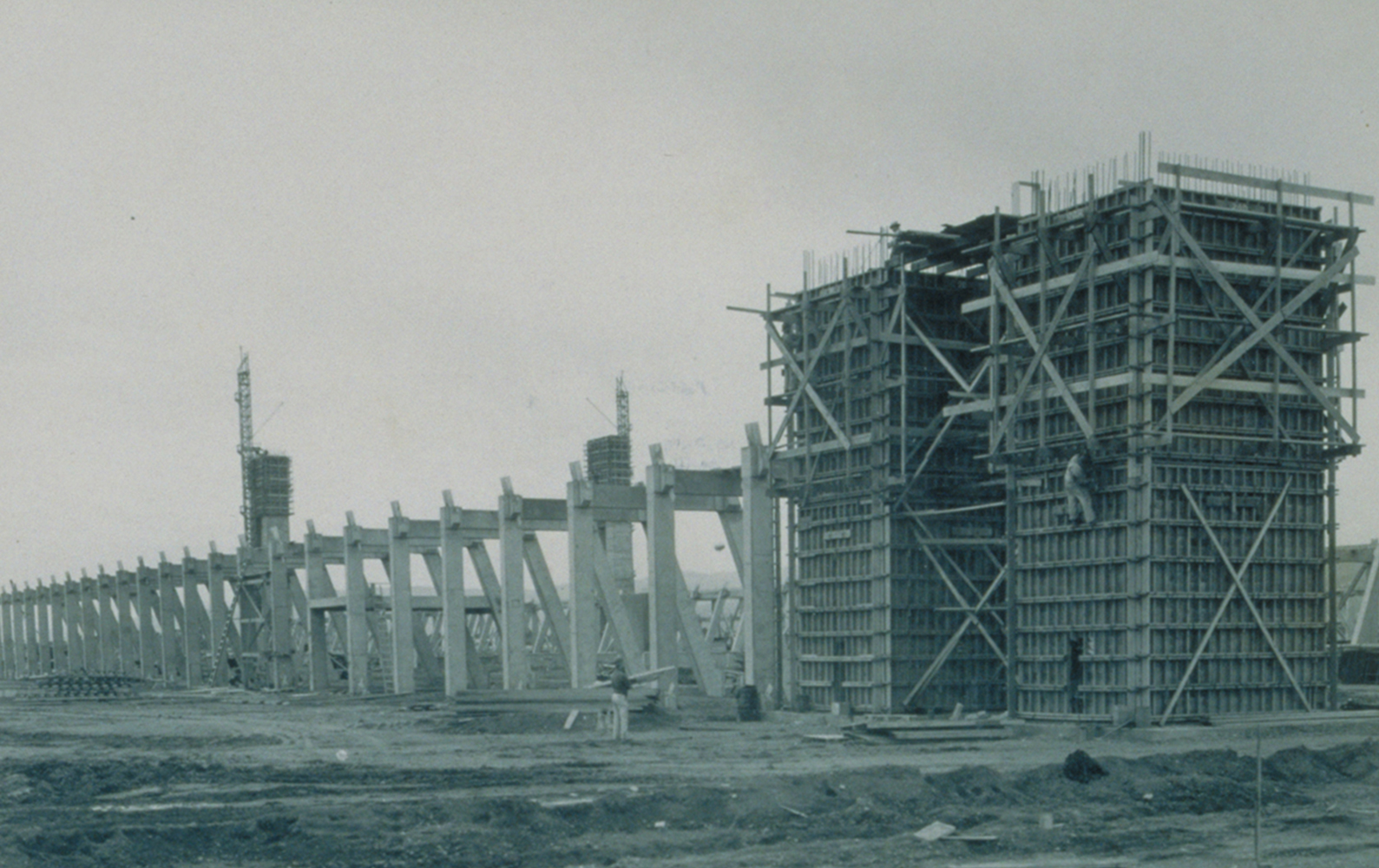
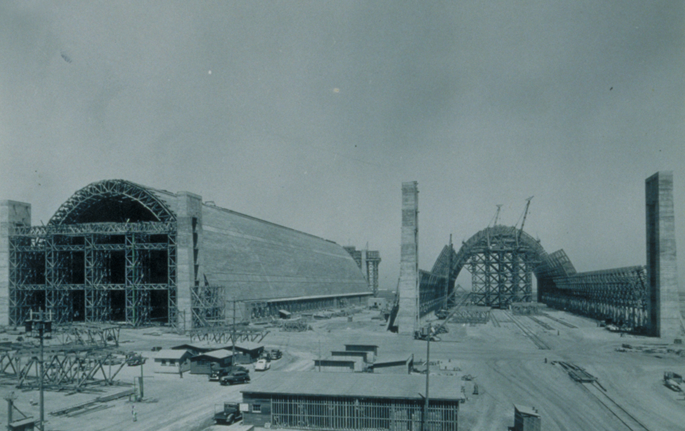
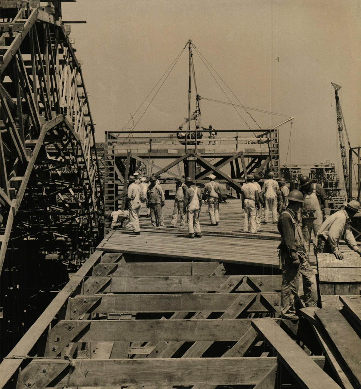
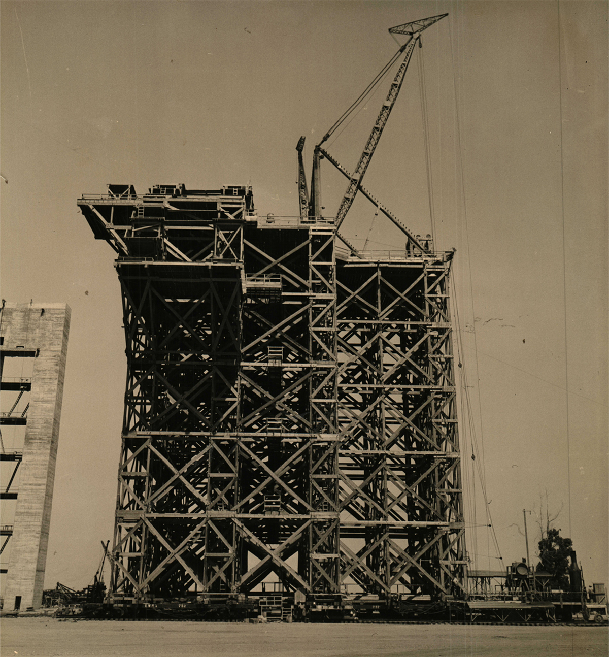
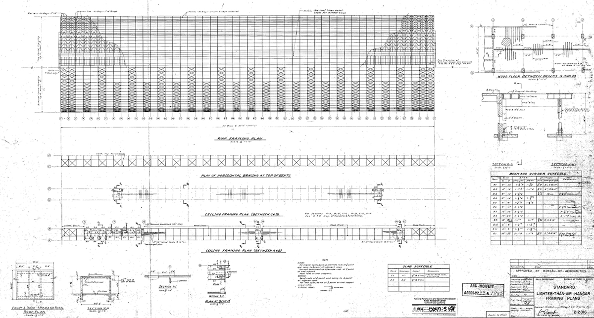
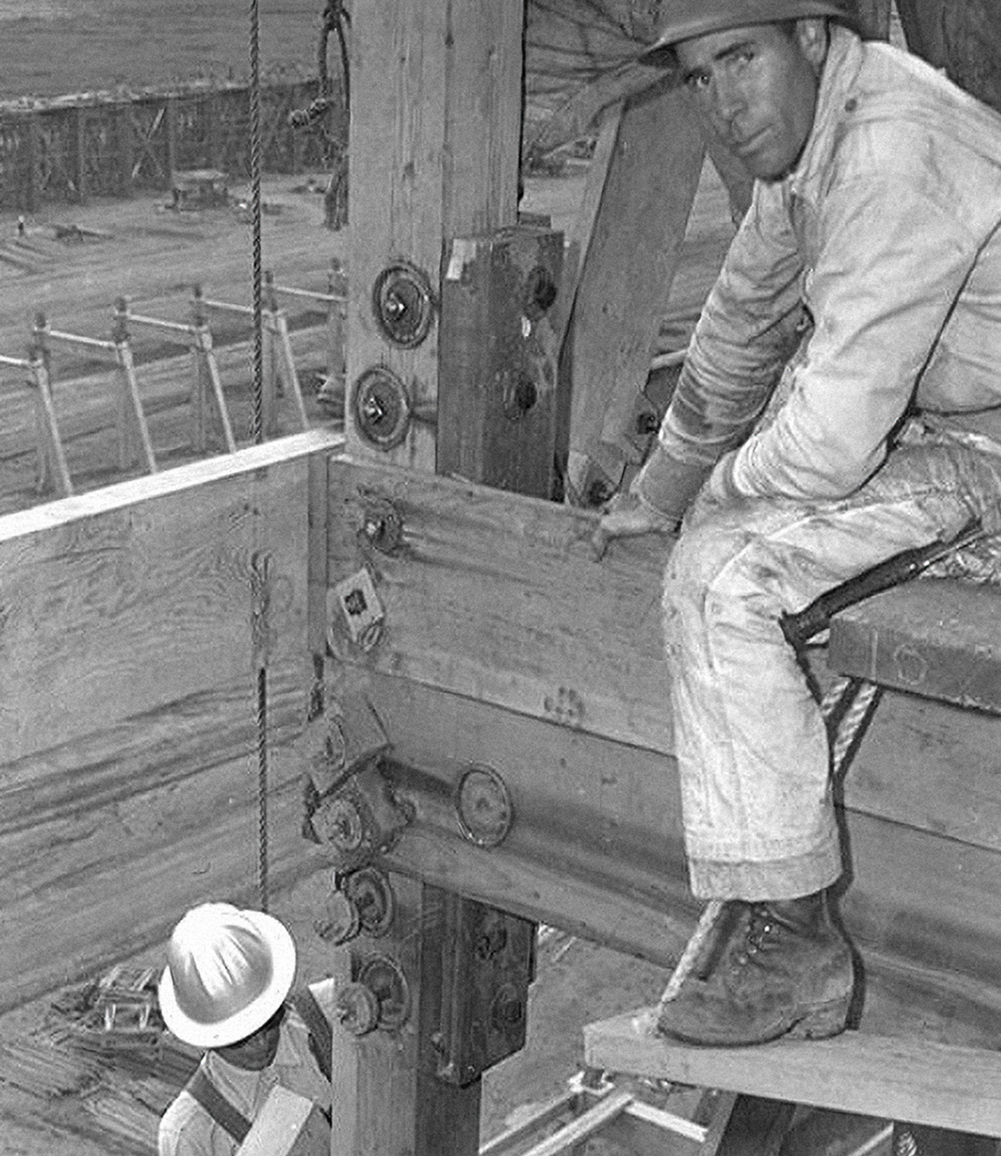
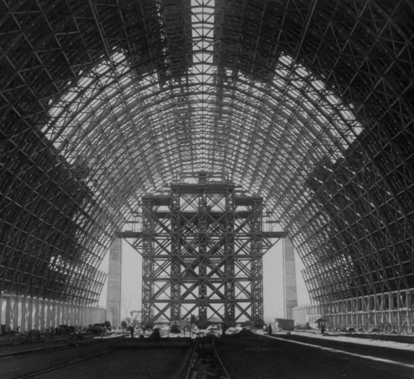
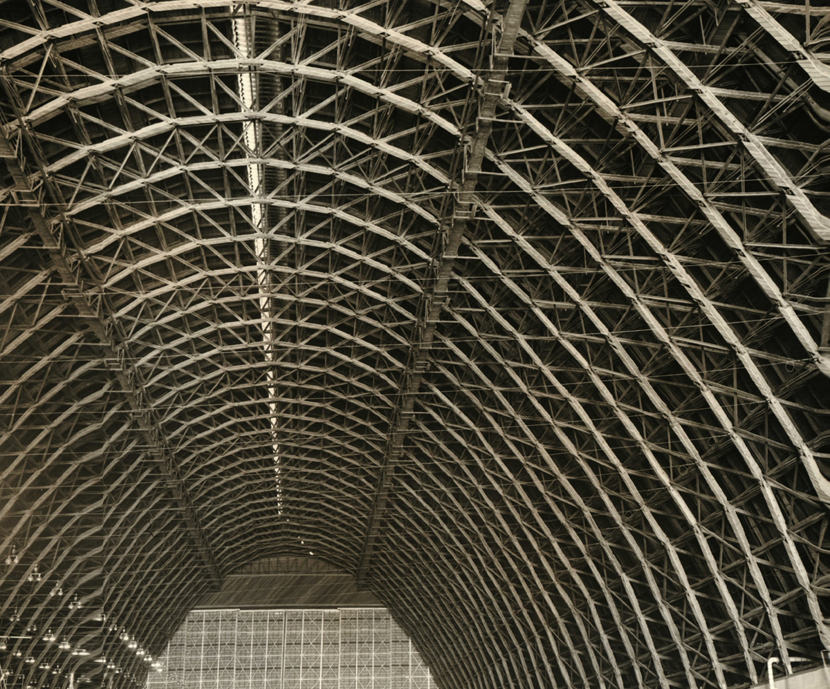
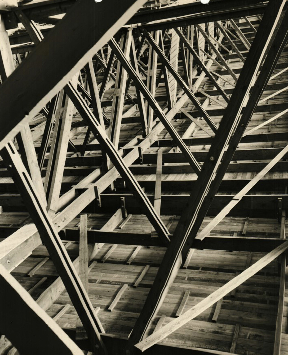
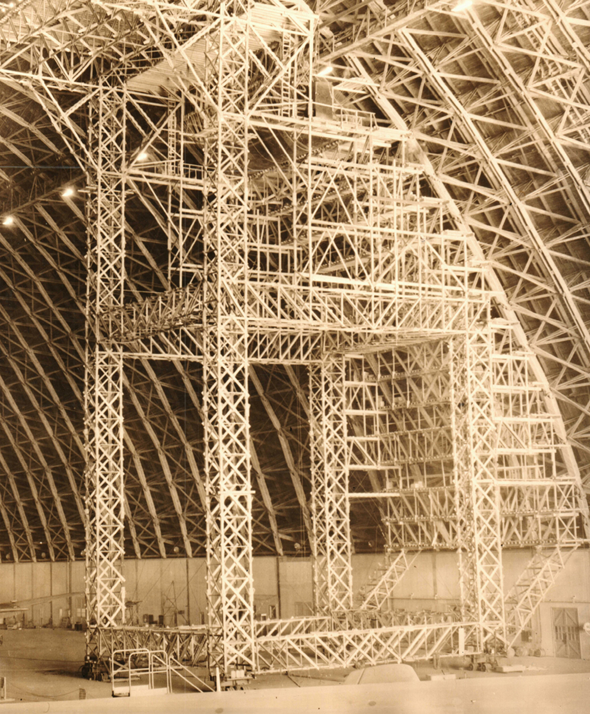
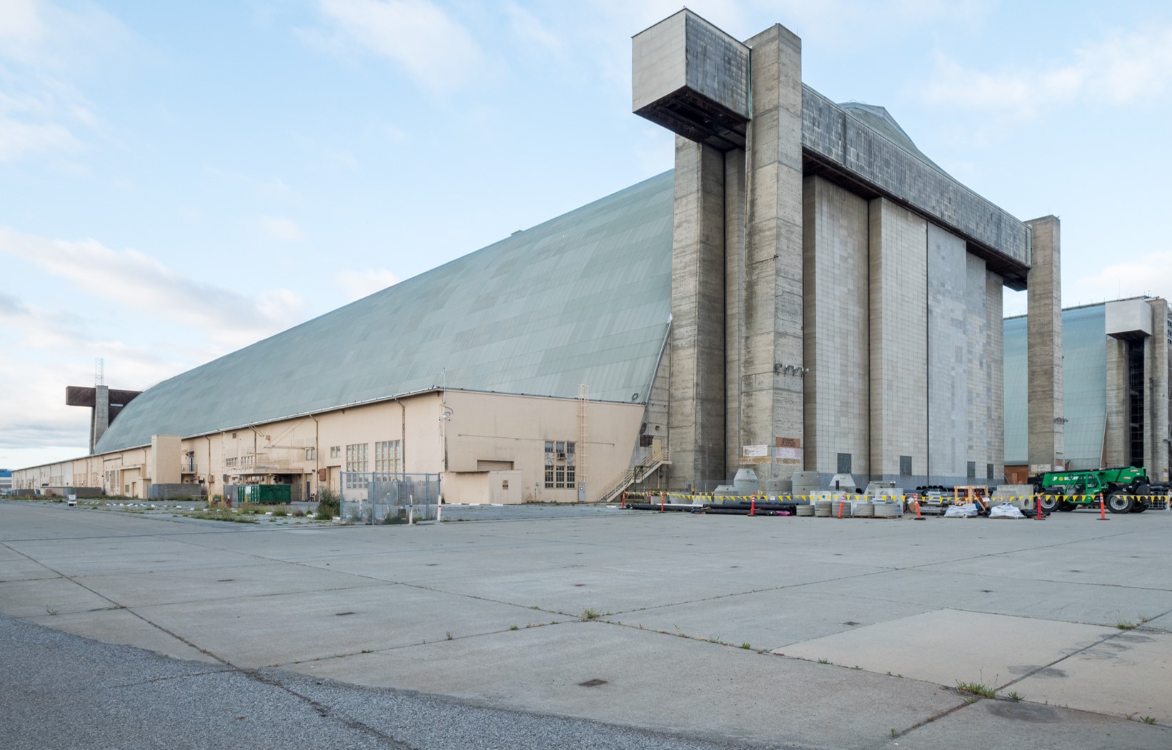
The monumental twin hangars were located only 170 feet apart. Each building was more than 1,000 feet long and 171 feet high. They were composed of 51 parabolic open-web timber arches, spaced 20 feet on center, resting on 25-foot-tall reinforced concrete bent frames. The wood trusses were fastened together with bolted steel plates and hoisted into place with a crane and traveler gantry that moved down the center of each building on a set of rails. The hangars’ extruded parabolic profiles reflect the curved form of the blimps that the buildings were designed to protect.

A construction worker, straddling a wood beam high above the Hangar 2 construction site, looks at the camera. A man in a hard hat is on the beam below.
Detail of the construction of the Traveler used in Hangar 2, Earl W. Heple & J.H. Pomeroy Inc., Contractors, U.S. Navy, 1943. Courtesy Moffett Field Historical Society Museum and National Archives and Records Administration, photo no. 71-CB-73C-12
An interior view of the partially covered wood trusses of Hangar 2. A large scaffolding fills the space below the arches at the end of the building.
Inside view of Hangar 2 looking south down the centerline toward the Traveler. Earl W. Heple & J.H. Pomeroy Inc., Contractors, U.S. Navy, 1943. Courtesy Moffett Field Historical Society Museum, photo no. SNVL 1738

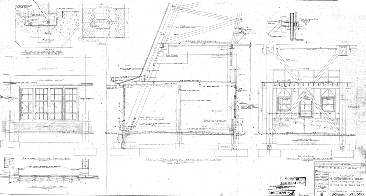
Hangar 2 is 297 feet wide and has an area of 347,000 square feet. Hangar 3 was 378 feet wide and had an area of 434,000 square feet. Flared outer walls helped to accommodate two levels of office, lab, shop, and storage spaces along the buildings’ long facades. A pair of catwalks provided access to the upper portions of the vast interior spaces.

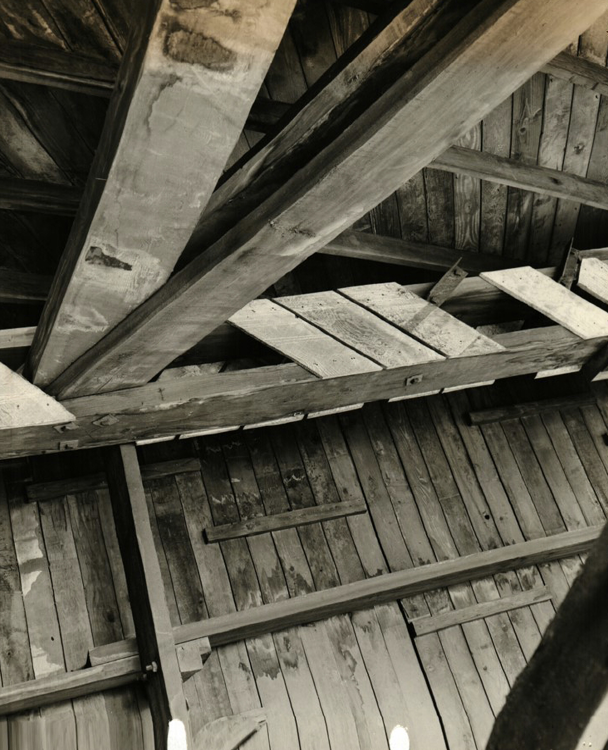
The hangars were each made with over 3 million board feet of Douglas Fir, which was chosen because it has a long-fiber structure that provides both strength and flexibility. Before they were assembled, all of the wood members were treated with creosote, a pine tar derivative used as a preservative to protect the material from termites and other pests. The timber elements were also made fire-resistant to guard against incendiary bombing.

A birds-eye view of the construction site of 2 nearly completed blimp hangars located side-by-side.
Aerial view of Hangars 2 and 3 under construction, U.S. Navy, 1943. Courtesy Moffett Field Historical Society, photo no. 361 1943
A view down the length of the long roof of Hangar 3 showing construction workers covering the exposed wood arch trusses with timber planks.
View of the top of the scaffolding used to put on the roof of Hangar 3, Earl W. Heple & J.H. Pomeroy Inc., Contractors, U.S. Navy, 1943. Courtesy Naval History & Heritage Command and Moffett Field Historical Society Museum, Seabee Archive, photo no. SNVL 1937
A dramatic exterior view of the end of Hangar 3 featuring the installed structural frames for its tall sliding door panels.
North end of Hangar 3 showing the doors erected and ready for covering, Earl W. Heple & J.H. Pomeroy Inc., Contractors, U.S. Navy, 1943. Courtesy Moffett Field Historical Society Museum, photo no. SNVL 2207

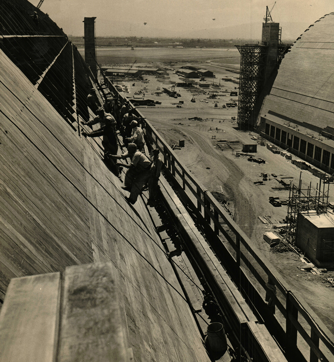
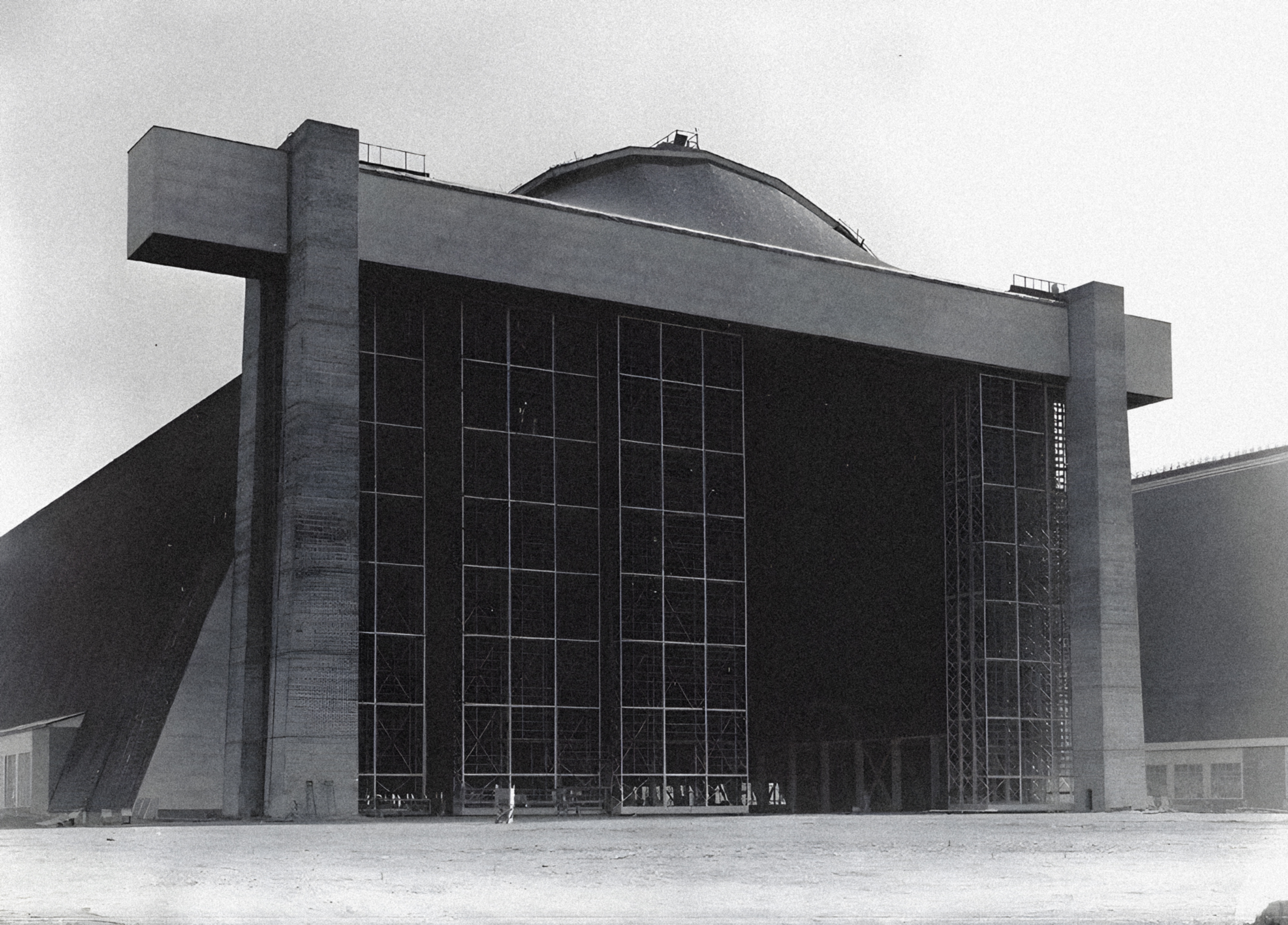
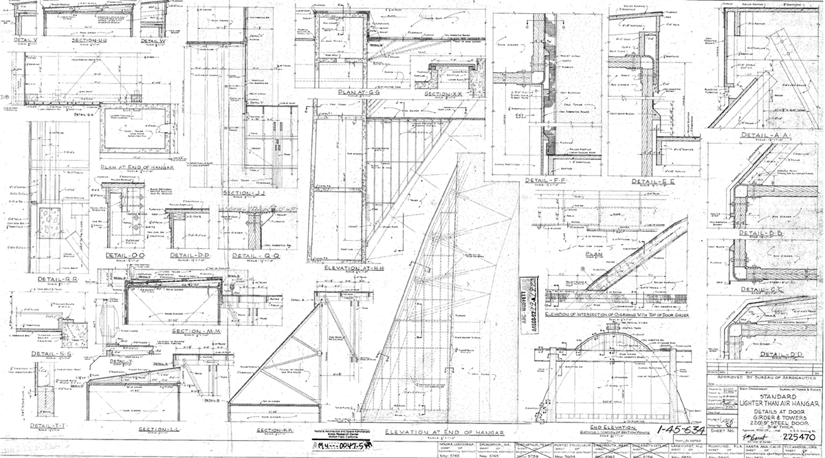
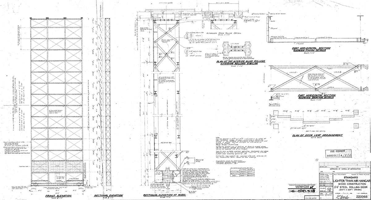
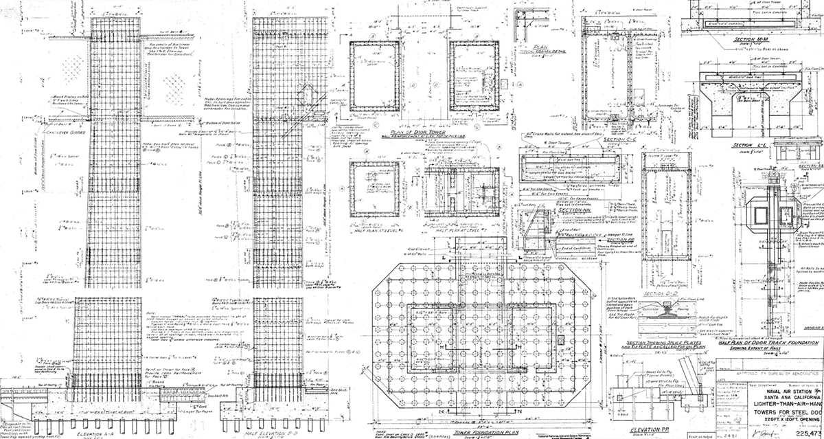
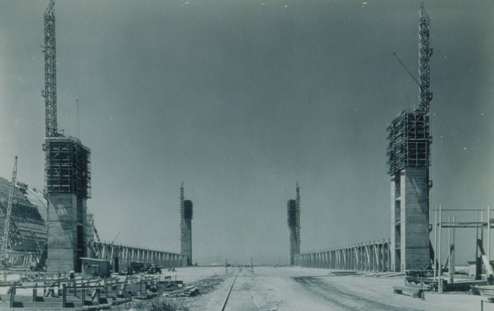
The 121-foot-tall doors on the north and south ends of each building were supported by a single 200-foot-long wood box beam resting on two cast-in-place concrete towers. The 147-foot-tall towers were structurally separate from the hangar’s timber truss system, in order to resist gravity and wind loads. A total of 816 concrete piles were used for the foundations of the hangar’s four towers. An interior ladder provided access to each tower’s eight internal platform levels.

The enormous entryways were crowned with clamshell domes that enclosed the space between the horizontal beam and the hangar’s curved roof line. The door assembly included six aluminum and wood frame sliding panels, each weighing 26 to 29 tons, that moved along a series of guide rails embedded in the concrete slab floor. To minimize the negative effects of unpredictable winds, the overlapping door system did not extend beyond the profile of the hangar.

The two-foot-three-inch thick foundation slab was made of 20-by-20-foot panels of poured-in-place and reinforced concrete separated by one-inch expansion joints. Rail tracks installed in the floors of Hangars 2 and 3 helped a small car with a mooring mast pull the blimps to safety from the circular landing pads located to the north and south of the buildings. A regular pattern of metal rings, called blimp tie-downs, was also attached to the concrete slab.

Improvements and Repairs

The development of Hangar 2 and Hangar 3 was part of the Navy’s Accelerated Public Works Program. Their expedited production schedule, due to World War II, prevented rigorous research and testing from being executed. The lack of in-depth analysis and detailed strategies for an innovative timber project of such an immense scale resulted in numerous issues during the project’s design and construction.

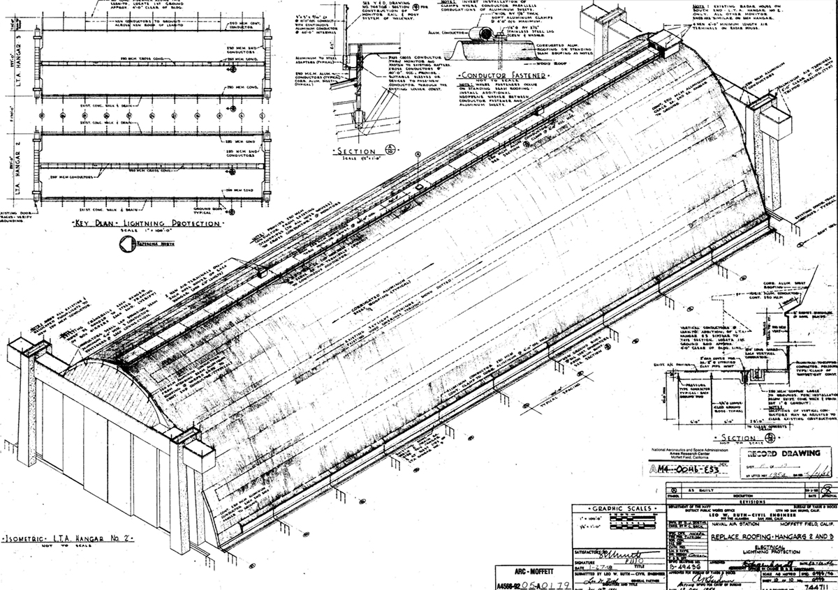
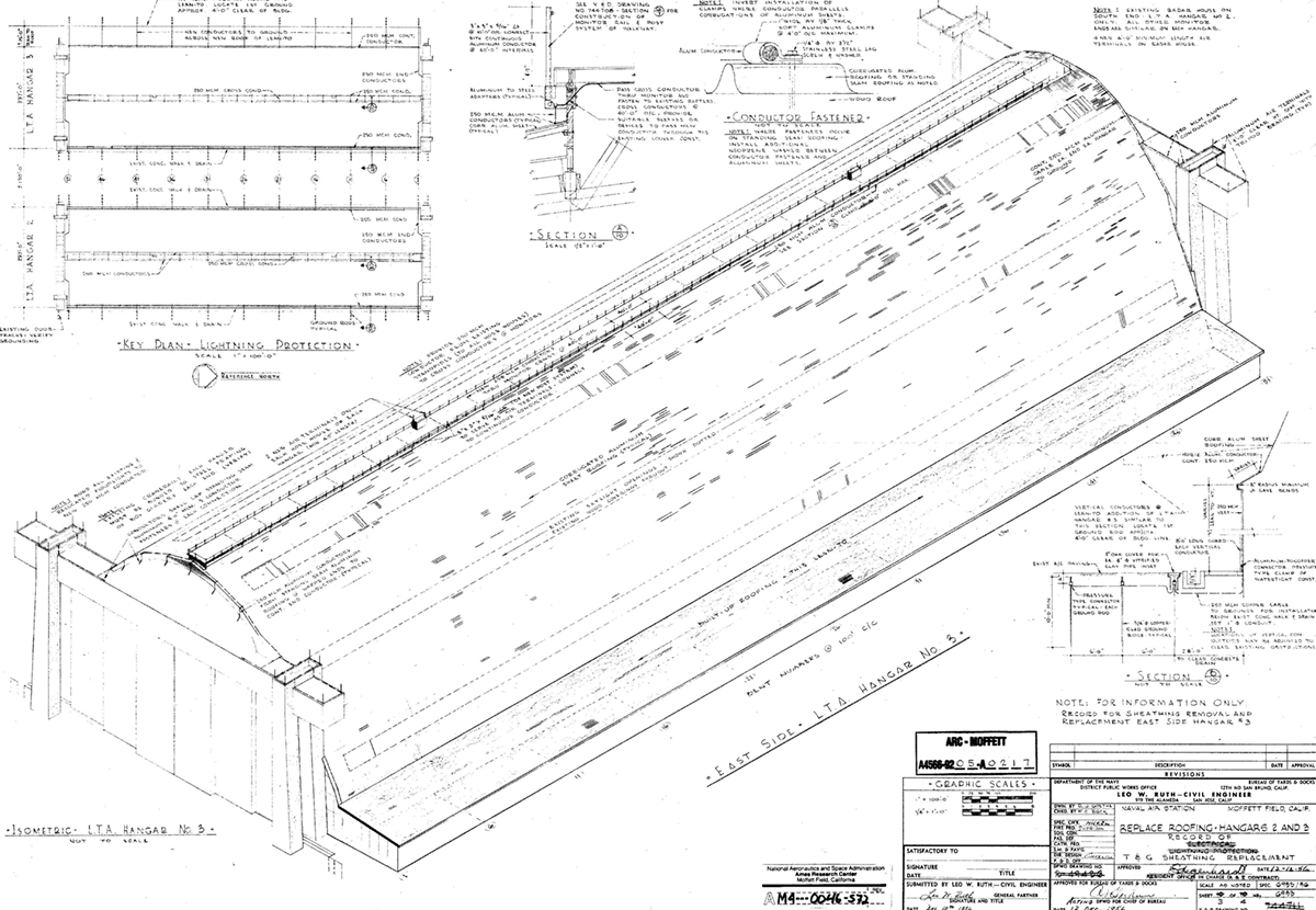
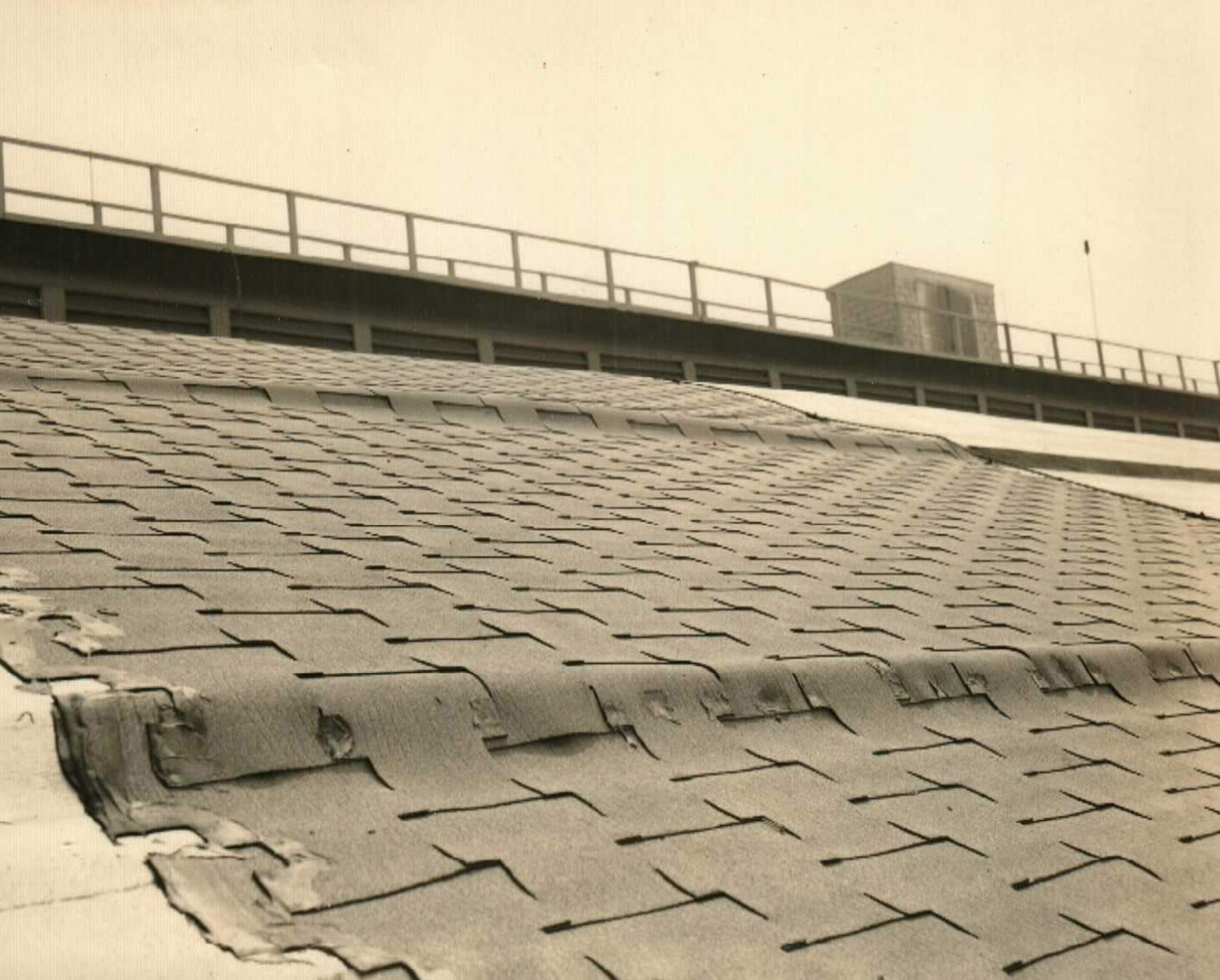
In 1945, a two-story annex that was 60 feet wide and 1,000 feet long was built on the east side of Hangar 3, in order to provide additional support and service areas. In 1956, the original tarpaper rolled roofing on each hangar was replaced with 466,000 square feet of green corrugated aluminum panels over straight wood sheathing. In 1946, just three years after the hangars were completed, an extensive remediation project was implemented to strengthen the trusses throughout each building. Wood battens were added to structural members to increase stability and prevent buckling. Timber knee-braces were also added to reduce the unbraced length of vertical web members. In the decades that followed, steel clamps, stitch bolts, glulam members, and steel pipe shores were added to Hangar 3, in an ongoing effort to stabilize the failing structure and prolong its lifespan.
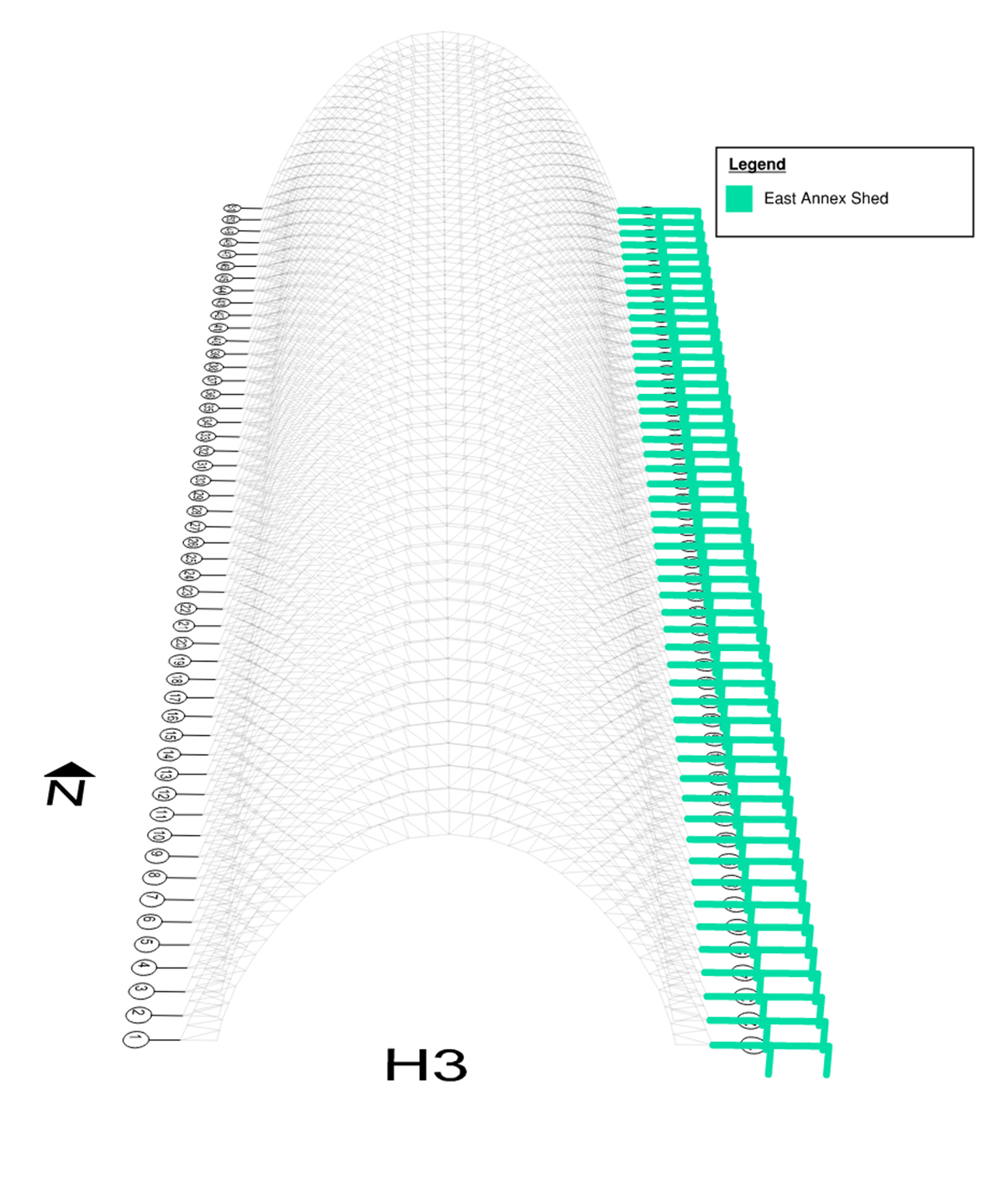
A 3D drawing of the entire length of Hangar 3 looking down on its parabolic arch trusses. The columns and beams of the annex on the east facade are green.
East Shed Annex
1945

Diagram from Hangar 3 Damage Progression & Repairs Timeline, KPFF, 2020. From MFA Hangar 3 Hazard Remediation Section 106 Technical Report, Appendix A.3, KPFF SHPO# NASA_2019_1216_001, Moffett Federal Airfield, Santa Clara County, California. Stantec Consulting Services, Inc., May 11, 2020. Prepared for the NASA Ames Research Center Historic Preservation Office. Page 92. Courtesy KPFF
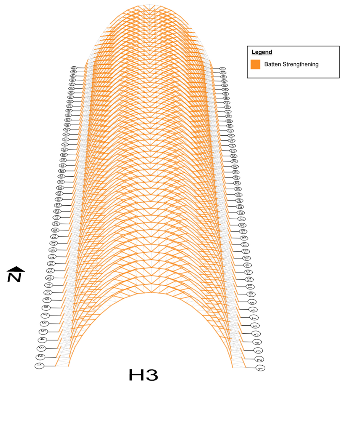
A 3D drawing of the entire length of Hangar 3 looking down on its parabolic arch trusses. The areas of the trusses that have been repaired are orange.
Batten Strengthening
1946

Diagram from Hangar 3 Damage Progression & Repairs Timeline, KPFF, 2020. From MFA Hangar 3 Hazard Remediation Section 106 Technical Report, Appendix A.3, KPFF SHPO# NASA_2019_1216_001, Moffett Federal Airfield, Santa Clara County, California. Stantec Consulting Services, Inc., May 11, 2020. Prepared for the NASA Ames Research Center Historic Preservation Office. Page 93. Courtesy KPFF
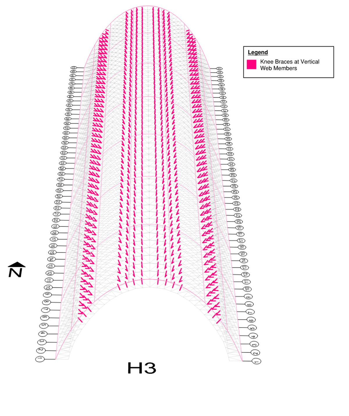
A 3D drawing of the entire length of Hangar 3 looking down on its parabolic arch trusses. The areas of the trusses that have been repaired are pink.
Knee Braces
1946

Diagram from Hangar 3 Damage Progression & Repairs Timeline, KPFF, 2020. From MFA Hangar 3 Hazard Remediation Section 106 Technical Report, Appendix A.3, KPFF SHPO# NASA_2019_1216_001, Moffett Federal Airfield, Santa Clara County, California. Stantec Consulting Services, Inc., May 11, 2020. Prepared for the NASA Ames Research Center Historic Preservation Office. Page 94. Courtesy KPFF
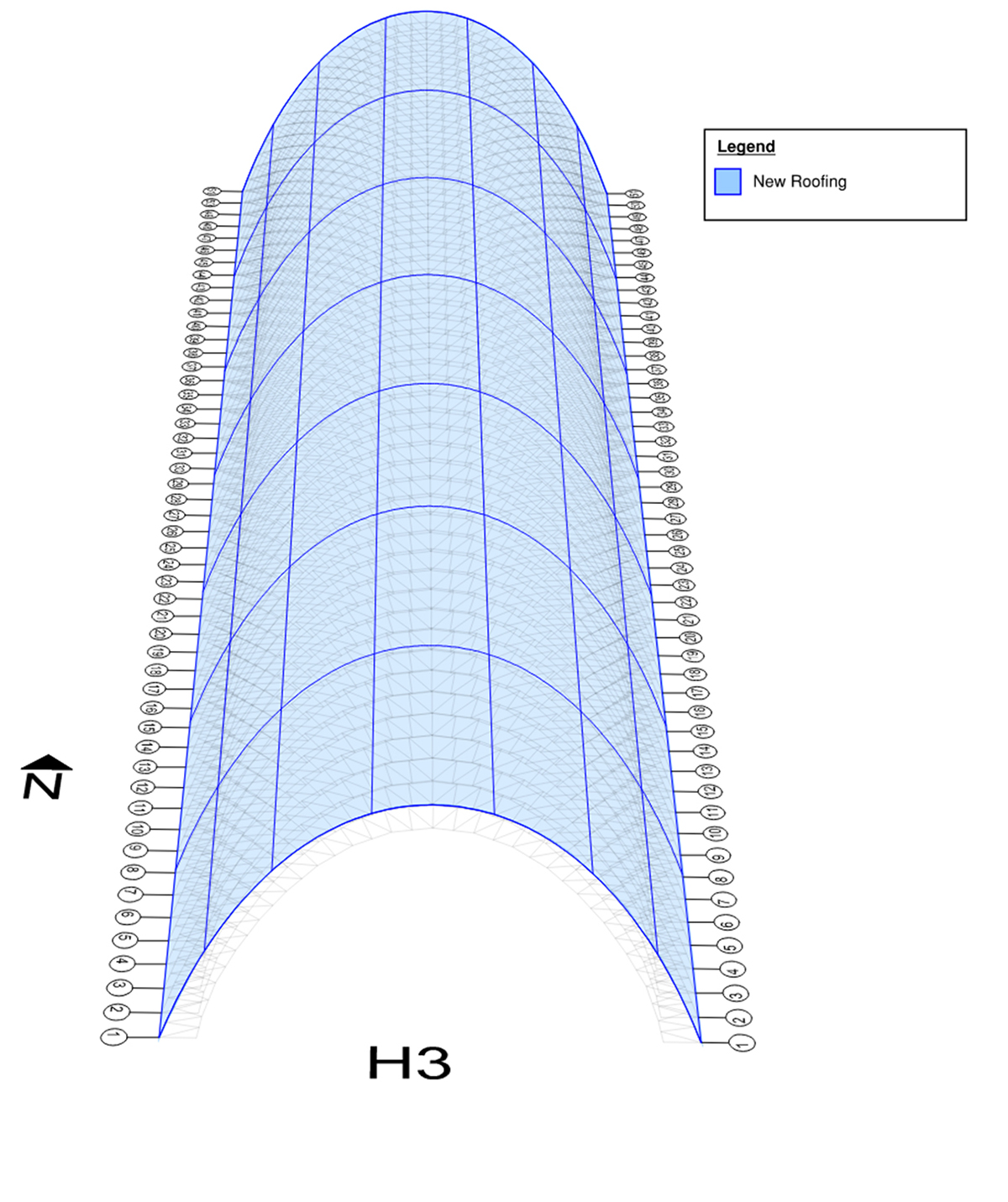
A 3D drawing of the entire length of Hangar 3 looking down on its parabolic arch trusses which are clad in a curved blue surface indicating the new roof.
Re-roofing
1956

Diagram from Hangar 3 Damage Progression & Repairs Timeline, KPFF, 2020. From MFA Hangar 3 Hazard Remediation Section 106 Technical Report, Appendix A.3, KPFF SHPO# NASA_2019_1216_001, Moffett Federal Airfield, Santa Clara County, California. Stantec Consulting Services, Inc., May 11, 2020. Prepared for the NASA Ames Research Center Historic Preservation Office. Page 95. Courtesy KPFF
An interior view down the length of Hangar 3 looking up at its wood parabolic arch trusses.
Inspection of Timber Airship Docks Nos. 2 and 3 at Naval Air Station, Moffett Field, California. Photographs which are intended to clarify the inspection report calling for corrective work. Hangar 3, general view showing doors closed on north end. J.H. Pomeroy Inc., Contractors, U.S. Navy, circa 1946. Courtesy Naval History & Heritage Command and Moffett Field Historical Society Museum, Seabee Archive, photo no. 12
A close-up view of the damaged condition of the wood trusses and the wood roof planks inside Hangar 3.
Inspection of Timber Airship Docks Nos. 2 and 3 at Naval Air Station, Moffett Field, California. Photographs which are intended to clarify the inspection report calling for corrective work. Hangar 3, showing location of lower chord inner, far, on arch no. 10, left side. Also showing location, of upper chord inner near, arch 43 left between panel points 17 and 18 on upper chord. J.H. Pomeroy Inc., Contractors, U.S. Navy, circa 1946. Courtesy Naval History & Heritage Command and Moffett Field Historical Society Museum, Seabee Archive, photo no. 7
A close-up view of the damaged condition of the wood trusses and the wood roof planks inside Hangar 3.
Inspection of Timber Airship Docks Nos. 2 and 3 at Naval Air Station, Moffett Field, California. Photographs which are intended to clarify the inspection report calling for corrective work. Hangar 3, arch no. 1 left. Upper chord near. Upper chord panel point zero to no. 2. Showing proximity to end wall of hangar. J.H. Pomeroy Inc., Contractors, U.S. Navy, circa 1946. Courtesy Naval History & Heritage Command and Moffett Field Historical Society Museum, Seabee Archive, photo no. 6
A tall, wide scaffolding tower on wheels waiting to be rolled into Hangar 3. It has a curved side that matches the parabolic arch trusses of the hangar.
Construction photograph of traveling scaffolding from Hangar 3, J.H. Pomeroy Inc., Contractors, U.S. Navy, 1946. Courtesy Naval History & Heritage Command and Moffett Field Historical Society Museum, Seabee Archive, photo no. 484 November 20, 1946
A tall, wide scaffolding tower inside the hangar. Its curved side mirrors the parabolic arch trusses of the hangar to efficiently fix the structure.
View of the timber moveable scaffolding used for the strengthening of Hangars 2 and 3 at Naval Air Station Moffett Field, California, J.H. Pomeroy Inc., Contractors, U.S. Navy, circa 1946. Courtesy Naval History & Heritage Command and Moffett Field Historical Society Museum, Seabee Archive, photo no. unknown
A close-up view of the new corrugated metal panels on the roof of Hangar 3.
Detail of the corrugated aluminum roof panels on Hangar 3, Naval Air Station Moffett Field, Stephen D. Schafer, 2018. Courtesy Library of Congress, Prints & Photographs Division, HAER, CA-335-B-9
A close-up view of the old interlocking shingles on the roof of Hangar 3.
Original interlocking shingles on the roof of Hangar 3, U.S. Navy, 1954. Courtesy Naval History & Heritage Command and Moffett Field Historical Society Museum, Seabee Archive, photo no. 9785-B
A wide view of the exterior corner of Hangar 3 with its doors closed and the two-story annex building along its long façade.
Oblique view of northeast corner of Hangar 3, Naval Air Station Moffett Field, Stephen D. Schafer, 2018. Courtesy Library of Congress, Prints & Photographs Division, HAER, CA-335-B-4

Lighter-Than-Air (LTA) Timber Hangars Designed with Standardized Plans

Architects
U.S. Navy Department Bureau of Yards and Docks


Supervisor
Captain Carl Trexel, Civil Engineer Corps, U.S. Navy


Design Manager
Commander E. H. Praeger, Civil Engineer Corps, U.S. Navy Reserve


Assistant Design Manager
Commander G.A. Hunt, Civil Engineer Corps, U.S. Navy Reserve


Principal Engineer
Arsham Amirikian


Number of nearly identical LTA timber hangars built between late 1942 and 1943
17


Number of U.S. Naval Air Stations with LTA timber hangars
10


Number of airships that could be based inside each hangar
6 to 10 depending on the airship type


Amount of lumber required to build each hangar
over 3 million FBM (foot board measure)


Hangars 2 & 3

Contractors
Earle W. Heple and J. H. Pomeroy Incorporated


Manufacturer of wood trusses
Timber Structures, Inc. of Portland, Oregon


Structure
51 parabolic Douglas Fir wood-trussed arches resting on concrete bent frames


Foundation
2-foot-3-inch concrete slab poured in a series of 20-foot by 20-foot panels separated by one-inch expansion joints


Roof
Corrugated aluminum siding over straight wood sheathing


Height of horizontal sliding doors
121 feet


Width of horizontal sliding doors

220 feet


Height of door towers
147 feet


Length of the wood box beam spanning the door towers
200 feet


Hangar 2

Length
1,075 feet


Width
297 feet


Height
171 feet


Area
347,000 square feet


Number of days to construct
372


Construction completed
1943


Cost
approximately $2.5 million


Hangar 3

Length
1,114 feet


Width
378 feet


Height
171 feet


Total area
434,000 square feet


Number of days to construct
208


Construction completed
1943


Cost
approximately $1.8 million


Designer of the Two-Story East Shed Annex
Leo W. Ruth, Civil Engineer, Navy Department Bureau of Yards and Docks


Length of East Shed Annex
1,000 feet


Width of East Shed Annex
62 feet


PAGE NAVIGATION
4 / 10 Sections